Home
About Us
Company Profile
Culture
Partners
Manufacturing
Products
Rolling Machine
Hydraulic Press
Profile Bending Machine
Shearing Machine
Bending Machine
Levelling machine
Solution
Solution
Customer Site
News
Company News
Industry News
Video
Service
Customer Service
Installation Training
Spare Part Service
FAQ
Download
Recruitment
Talent Concept
Job Opportunity
Contact Us
CN
Search
Rolling Machine

Products

Provider of comprehensive solutions for sheet metal forming machinery
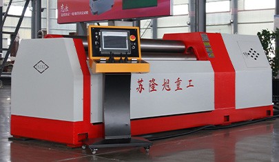
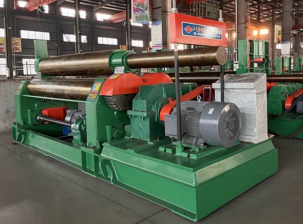
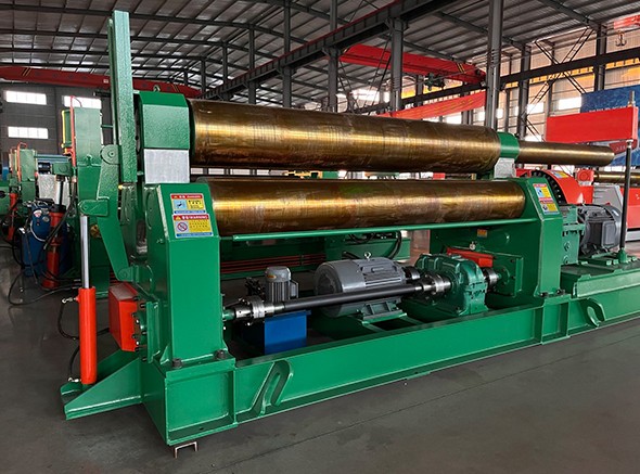
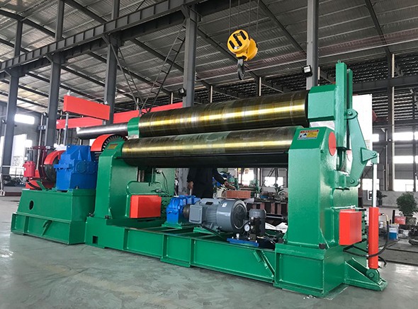
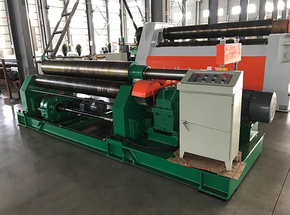
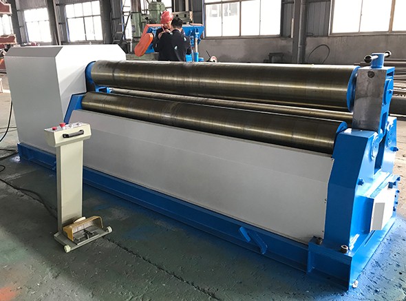
W11-30x2500 Mechanical symmetrical plate rolling machine
The mechanism is in the form of three-roll symmetry, the upper roll in the central symmetric position of the two rolls for vertical lifting movement, through the screw master worm transmission, the two rolls for rotating movement, through the output gear of the reducer and the lower roll gear mesh, to provide torque for the coil sheet ...
Product introduction:
The mechanism is in the form of three-roll symmetry, the upper roll in the central symmetric position of the two rolls for vertical lifting movement, through the screw master worm transmission, the two rolls for rotating movement, through the output gear of the reducer and the lower roll gear mesh, to provide torque for the coil sheet.
 
The two lower rollers are active rollers, driven by the main motor, coupling, reducer and open gear pair. When the upper roll is working, it is driven by the friction between the steel plates. At the same time, as a driven shaft, it plays the role of adjusting extrusion. Controlled by a separate transmission system, the main components are: upper roller lifting motor, reducer, worm gear pair, nut. When working, the worm gear pair rotates the inner nut of the worm gear to make the screw and the bearing seat of the upper roll move up and down. The two lower rollers can rotate positively and negatively in two directions, and the lower rollers roll repeatedly under the pressure of the upper rollers, so that the sheet material reaches the required curvature and forms the expected shape.
Specifications:

Specification and model

Maximum thickness(mm)

Maximum width(mm)

Yield limit
(MPa)

Coil speed
(m/min)

Full load minimum diameter(mm)

Upper shaft diameter
(mm)

Lower shaft diameter
(mm)

Two lower axis center distance
(mm)

Main motor power
(kw)

W11-6×1500

6

1500

245

5

450

160

160

250

4

W11-6×2000

6

2000

245

4.5

450

185

170

250

5.5

W11-3×3200

3

3200

245

4.5

450

185

170

250

5.5

W11-12×2000

12

2000

245

4

600

240

180

280

7.5

W11-8×2500

8

2500

245

4

600

240

180

280

7.5

W11-12×3000

12

3000

245

4

700

280

250

339

11

W11-16×2500

16

2500

245

4

700

280

240

359

11

W11-20×2000

20

2000

245

4

700

280

240

359

11

W11-25×2000

25

2000

245

4

850

330

270

440

15

W11-20×2500

20

2500

245

4

850

340

280

440

15

W11-16×3000

16

3000

245

4

850

340

280

440

15

W11-25×2500

25

2500

245

4

1200

360

290

480

22